Plug and Play
http://baike.baidu.com/view/33701.htm
编辑
1解析编辑
2应用编辑
3由来编辑
Legacy Plug and Play
http://en.wikipedia.org/wiki/Legacy_Plug_and_Play
The term Legacy Plug and Play,[1] also shortened to PnP,[2] describes a series of specifications and Microsoft Windows features geared towards operating system configuration of devices. The standards were primarily aimed at the IBM PC standard bus, later dubbed ISA. Related specifications are also defined for the common external or specialist busses commonly attached via ISA at the time of development, including RS-232 and parallel port devices.
As a Windows feature, Plug and Play refers to operating system functionality that supports connectivity, configuration and management with native plug and play devices.[3]Originally considered part of the same feature set as the specifications, Plug and Play in this context refers primarily to the responsibilities and interfaces associated with Windows driver development.[4]
Plug and Play allows for detection of devices without user intervention, and occasionally for minor configuration of device resources, such as I/O ports and device memory maps. PnP is a specific set of standards, not be confused with the generic term plug and play, which describes any hardware specification that alleviates the need for user configuration of device resources.[5]
Contents
[hide]
- 1 Overview
- 2 Specifications
- 3 Requirements
- 4 Hardware identification
- 5 See also
- 6 References
- 7 External links
Overview[edit]
The Plug and Play standard requires configuration of devices to be handled by system firmware, which then provides details of resources allocations to the operating system. The process is invoked at boot time. When the computer is first turned on, compatible devices are identified and assigned non-conflicting addresses and interrupt request numbers.
The term Plug and Play was first used by Microsoft in reference to their Windows 95 product. Other operating systems, such as AmigaOS Autoconfig and the Mac OS NuBussystem, had already supported such features for some time (under various names, or no name[6]), but the term plug and play gradually became universal due to worldwide acceptance of Windows.[citation needed]
Typically, non-PnP devices need to be identified in the computer's BIOS setup so that the PnP system will not reassign those devices. Problems in the interactions between legacy non-PnP devices and the PnP system can cause it to fail, leading to this technology having historically been referred to as "plug and pray".[2]
Specifications[edit]
Legacy Plug and Play was defined in Microsoft and Intel specifications, which proposed changes to legacy hardware, as well as the BIOS to support operating system-bound discovery of devices. These roles were later assumed by the ACPI standard,[1] which also moves support for power management and configuration into the operating system, as opposed to the firmware as previously required by the "Plug and Play BIOS" and APM specifications. The following standards compose what Microsoft describe as Legacy Plug and Play, as opposed to native Plug-and-Play specifications such as PCI and USB.
- Plug and Play BIOS Specification
- Plug and Play ISA Specification
- Plug and Play Design Specification for IEEE 1394
- Plug and Play External COM Device Specification
- Plug and Play Parallel Port Device Specification
- Plug and Play SCSI Specification
- Legacy Plug and Play Guidelines
Apart from the Plug and Play BIOS Specification, all standards are still supported by Microsoft.[1] However, support for them as opposed to Advanced Configuration and Power Interface will be removed in future version of Windows.[7]
Requirements[edit]
A PnP-compatible computer must meet three requirements:
- The OS must be PnP-compatible.
- The BIOS must support PnP.
- The device to be installed must be a PnP device.
Hardware identification[edit]
Plug-and-play hardware typically also requires some sort of ID code that it can supply, in order for the computer software to correctly identify it.
This ID code system was not integrated into the early Industry Standard Architecture (ISA) hardware common in PCs when Plug and Play was first introduced. ISA Plug and Play caused some of the greatest difficulties that made PnP initially very unreliable. This led to the derisive term "Plug and Pray", since I/O addresses and IRQ lines were often set incorrectly in the early days. Later computer buses like MCA, EISA and PCI (which was becoming the industry standard at that time) integrated this functionality.
Finally, the operating system of the computer needs to be able to handle these changes. Typically, this means looking for interrupts from the bus saying that the configuration has changed, and then reading the information from the bus to locate what happened. Older bus designs often required the entire system to be read in order to locate these changes, which can be time consuming for lots of devices. More modern designs use some sort of system to either reduce or eliminate this "hunt"; for example, USB uses a hub system for this purpose.
When the change is located, the OS then examines the information in the device to figure out what it is. It then has to load up the appropriate device drivers in order to make it work. In the past, this was an all-or-nothing affair, but modern operating systems often include the ability to find the proper driver on the Internet and install it automatically.
Plug and play
http://en.wikipedia.org/wiki/Plug_and_play
In computing, a plug and play device or computer bus, is one with a specification that facilitates the discovery of a hardware component in a system without the need for physical device configuration or user intervention in resolving resource conflicts.[1][2]
Plug and play devices can be due to boot-time assignment of device resources and to hotplug systems such as USB and IEEE 1394 (FireWire).[3]
Contents
[hide]
- 1 History of device configuration
- 2 First attempts at self-configuration
- 2.1 NuBus
- 2.2 Zorro bus
- 2.3 Micro-Channel Architecture
- 3 ISA and PCI self-configuration
- 4 Plug and Play
- 5 Current plug and play interfaces
- 6 See also
- 7 References
- 8 External links
History of device configuration[edit]
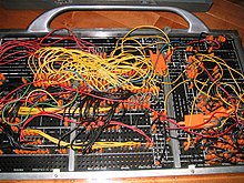

IBM 402 Accounting Machine control panel wiring. This control panel was labeled "profit & loss summary".
In the beginnings of data processing technology, the hardware was just a collection of modules, and the functions of those modules had to be linked to accommodate different calculating operations. This linking was usually done by connecting some wires between modules and disconnecting others. For many mechanical data processing machines, such as the IBM punched card accounting machines, their calculating operations were directed by the use of a quick-swap control panel wired to route signals between module sockets.
As general purpose computing devices developed, these connections and disconnections were instead used to specify locations in the system address space where an expansion device should appear, in order for the device to be accessible by the central processing unit. If two or more of the same type of device were installed in one computer, it would be necessary to assign the second device to a separate, non-overlapping region of the system address space so that both could be accessible at the same time.

Apple II serial interface card that required cutting and soldering to reconfigure. The user would cut the wire trace between the >< cones at X1 and X3 and solder the <> cones together at X2 and X4. Located vertically near center of board.
Some early microcomputing devices such as the Apple II sometimes required the end-user to physically cut some wires and solder others together to make configuration changes. The changes were intended to be largely permanent for the life of the hardware.
As computers became more accessible to the general public, the need developed for more frequent changes to be made by computer users unskilled with using soldering irons. Rather than cutting and soldering connections, configuration was accomplished by jumpers orDIP switches.

|

|
| Left: Jumper blocks of various sizes,Right: a slide-style DIP switch with 8 switches | |
However, the process of configuring devices manually using jumpers or DIP switches could be quite difficult, and there was usually no forgiveness for technical inexperience. Incorrect settings could render either the whole system or just the expansion device completely or partially inoperable. Some settings such as for interrupts (IRQ) or direct memory access (DMA) required knowledge of what configuration had been previously manually assigned to other devices, as well as what settings the main system itself may be using. The system might still seem to work properly with an incorrect setting, until the IRQ or DMA is actually needed and the entire system suddenly freezes and must be reset.
First attempts at self-configuration[edit]
As computing devices spread further out into the general population, there was ever greater pressure developing to automate this configuration process, and relieve the end-user from the hassle and complexity of having to manually assign these many complex settings.
NuBus[edit]

A NuBus expansion card without jumpers or DIP switches.
In 1984, the NuBus architecture was developed by the Massachusetts Institute of Technology (MIT) as a platform agnostic peripheral interface that fully automated device configuration. The specification was sufficiently intelligent that it could work with both big endian and little endian computer platforms that had previously been mutually incompatible. However, this agnostic approach increased interfacing complexity and required support chips on every device which in the 1980s was expensive to do, so the technology did not gain widespread support.
Zorro bus[edit]
In 1984, Commodore developed the AutoConfig protocol and the Zorro expansion bus for its Amiga line of expandable computers. The first public appearance was in the CES computer show at Las Vegas in 1985, with the so-called "Lorraine" prototype. Like NuBus, Zorro devices had absolutely no jumpers or DIP switches. The Zorro architecture did not spread to general computing use outside of the Amiga product line, but was eventually upgraded for the later iteration of Amiga computers.
Micro-Channel Architecture[edit]

An MCA expansion card without jumpers or DIP switches.
In 1987, IBM released an update to the IBM PC known as the Personal System/2 line of computers using the Micro Channel Architecture. The PS/2 was capable of totally automatic self-configuration. Every piece of expansion hardware was issued with a floppy disk containing a special file used to auto-configure the hardware to work with the computer. The user would install the device, turn on the computer, load the configuration information from the disk, and the hardware automatically assigned interrupts, DMA, and so forth.
However, the disks posed a problem if they were damaged or lost, as the only options at the time to obtain replacements was via postal mail or IBM's dialup BBS service. Without the disks, any new hardware would be completely useless and the computer would not boot at all until the unconfigured device was removed.
Microchannel did not gain widespread support, because IBM wanted to exclude clone manufacturers from this next generation computing platform. Anyone developing for MCA had to sign non-disclosure agreements and pay royalties to IBM for each device sold, putting a price premium on MCA devices. End-users and the clone manufacturers revolted against IBM and developed their own open standards bus, known as EISA. Consequently, MCA receded in use except in IBM's mainframes.
ISA and PCI self-configuration[edit]
In time, many Industry Standard Architecture (ISA) cards incorporated, through proprietary and varied techniques, hardware to self-configure or to provide for software configuration; often, the card came with a configuration program on disk that could automatically set the software-configurable (but not itself self-configuring) hardware. Some cards had both jumpers and software-configuration, with some settings controlled by each; this compromise reduced the number of jumpers that had to be set, while avoiding great expense for certain settings, e.g. nonvolatile registers for a base address setting. The problems of required jumpers continued on, but slowly diminished as more and more devices, both ISA and other types, included extra self-configuration hardware. However, these efforts still did not solve the problem of making sure the end-user has the appropriate software driver for the hardware.
ISA PnP or (legacy) Plug & Play ISA was a plug-n-play system that used a combination of modifications to hardware, the system BIOS, and operating system software to automatically manage resource allocations. It was superseded by the PCI bus during the mid-1990s.
Plug and Play[edit]
In 1995, Microsoft released Windows 95, which tried to fully automate device detection and configuration as much as possible, but could still fall back to manual settings if necessary. During the initial install process of Windows 95, it would attempt to automatically detect all devices installed in the system. Since full auto-detection of everything was a new process without full industry support, the detection process constantly wrote to a progress tracking log file during the detection process. In the event that device probing would fail and the system would freeze, the end-user could reboot the computer, restart the detection process, and the installer would use the tracking log to skip past the point that caused the previous freeze.
At the time, there could be a mix of devices in a system, some capable of automatic configuration, and some still using fully manual settings using jumpers and DIP switches. The old world of DOS still lurked underneath Windows 95, and systems could be configured to load devices three different ways:
- through Windows 95 device manager drivers only
- using DOS drivers loaded in the CONFIG.SYS and AUTOEXEC.BAT configuration files
- using both DOS drivers and Windows 95 device manager drivers together
Microsoft could not assert full control over all device settings, so configuration files could include a mix of driver entries inserted by the Windows 95 automatic configuration process, and could also include driver entries inserted or modified manually by the computer users themselves. The Windows 95 device manager also could offer users a choice of several semi-automatic configurations to try to free up resources for devices that still needed manual configuration.

An example of an ISA interface card with extremely limited interrupt selection options, a common problem on PC ISA interfaces.
Kouwell KW-524J dual serial, dual parallel port, 8-bit ISA, manufactured in 1992:
* Serial 1: IRQ 3/4/9
* Serial 2: IRQ 3/4/9
* Parallel 1: IRQ 5/7
* Parallel 2: IRQ 5/7
(There is no technical limitation that 3,4,5,7,9 could not all be selectable choices for each port.)
Also, although some later ISA devices were capable of automatic configuration, it was common for PC ISA expansion cards to limit themselves to a very small number of choices for interrupt request lines. For example, a network interface might limit itself to only interrupts 3, 7, and 10, while a sound card might limit itself to interrupts 5, 7, and 12. This results in few configuration choices if some of those interrupts are already used by some other device.
The hardware of PC computers additionally limited device expansion options because interrupts could not be shared, and some multifunction expansion cards would use multiple interrupts for different card functions, such as a dual serial port card requiring a separate interrupt for each serial port.
Because of this complex operating environment, the autodetection process sometimes produced incorrect results, especially in systems with large numbers of expansion devices. This led to device conflicts within Windows 95, resulting in devices which were supposed to be fully self-configuring failing to work. The unreliability of the device installation process led to that Plug and Play was sometimes referred to as Plug and Pray.
Up until about 2000, PC computers could still be purchased with a mix of ISA and PCI slots, so it was still possible that manual ISA device configuration might be necessary. But with successive releases of new operating systems like Windows 2000 and Windows XP, Microsoft had sufficient clout to say that drivers would not be provided for older devices that did not support auto-detection. In some cases, the user was forced to purchase new expansion devices or a whole new system to support the next operating system release.
Current plug and play interfaces[edit]
Several completely automated computer interfaces are currently used, each of which requires no device configuration by the computer user, and the only task of the user is to install software for the self-configuring devices.
- IEEE 1394 (FireWire)
- PCI, Mini PCI
- PCI Express, Mini PCI Express
- PCMCIA, PC Card, ExpressCard
- USB
For most of these interfaces, very little technical information is available to the end-user about the performance of the interface. Although both FireWire and USB have bandwidth that must be shared by all devices, most modern operating systems are unable to monitor and report the amount of bandwidth being used or available, or report activity on what devices are currently using the interface.
Plug and Play
The large variety of different cards that can be added to PCs to expand their capabilities is both a blessing and a curse. As you can see from the other sections that have discussed system resources, configuring the system and dealing with resource conflicts is part of the curse of having so many different non-standard devices on the market. Dealing with these issues can be a tremendously confusing, difficult and time-consuming task. In fact, many users have stated that this is the single most frustrating part of owning and maintaining a PC, or of upgrading the PC's hardware.
In an attempt to resolve this ongoing problem, the Plug and Play (also called PnP) specification was developed by Microsoft with cooperation from Intel and many other hardware manufacturers. The goal of Plug and Play is to create a computer whose hardware and software work together to automatically configure devices and assign resources, to allow for hardware changes and additions without the need for large-scale resource assignment tweaking. As the name suggests, the goal is to be able to just plug in a new device and immediately be able to use it, without complicated setup maneuvers.
A form of Plug and Play was actually first made available on the EISA and MCA buses many years ago. For several reasons, however, neither of these buses caught on and became popular. PnP hit the mainstream in 1995 with the release of Windows 95 and PC hardware designed to work with it.
Requirements for Plug and Play
Automatically detecting and configuring hardware and software is not a simple task. To perform this work, cooperation is required from several hardware and software areas. The four "partners" that must be Plug and Play compliant in order for it to work properly are:
- System Hardware: The hardware on your system, through the system chipset and system bus controllers, must be capable of handling PnP devices. For modern PCI-based systems this is built in, as PCI was designed with PnP in mind. Most PCI-based systems also support PnP on their ISA bus, with special circuitry to link the two together and share resource information. Older PCs with ISA-only or VL-bus system buses generally do not support Plug and Play.
- Peripheral Hardware: The devices that you are adding into the system must themselves be PnP compatible. PnP is now supported for a wide variety of devices, from modems and network cards inside the box to printers and even monitors outside it. These devices must be PnP-aware so that they are capable of identifying themselves when requested, and able to accept resource assignments from the system when they are made.
- The System BIOS: The system BIOS plays a key role in making Plug and Play work. Routines built into the BIOS perform the actual work of collecting information about the different devices and determining what should use which resources. The BIOS also communicates this information to the operating system, which uses it to configure its drivers and other software to make the devices work correctly. In many cases older PCs that have an outdated BIOS but otherwise have support for PnP in hardware (PCI-based Pentiums produced between 1993 and 1995 are the prime candidates) can be made PnP-compliant through a BIOS upgrade.
- The Operating System: Finally, the operating system must be designed to work with the BIOS (and thus indirectly, with the hardware as well). The operating system sets up any low-level software (such as device drivers) that are necessary for the device to be used by applications. It also communicates with the user, notifying him or her of changes to the configuration, and allows changes to be made to resource settings if necessary. Currently, the only mainstream operating system with full PnP support is Windows 95.
As you can see, you need a lot for Plug and Play to work, and this is why the vast majority of older systems (pre-1996) do not properly support this standard.
Plug and Play Operation
Most of the actual work involved in making Plug and Play function is performed by the system BIOS during the boot process. At the appropriate step of the boot process, the BIOS will follow a special procedure to determine and configure the Plug and Play devices in your system. Here is a rough layout of the steps that the BIOS follows at boot time when managing a PCI-based Plug and Play system:
- Create a resource table of the available IRQs, DMA channels and I/O addresses, excluding any that are reserved for system devices.
- Search for and identify PnP and non-PnP devices on the PCI and ISA buses.
- Load the last known system configuration from the ESCD area stored in non-volatile memory.
- Compare the current configuration to the last known configuration. If they are unchanged, continue with the boot; this part of the boot process ends and the rest of the bootup continues from here.
- If the configuration is new, begin system reconfiguration. Start with the resource table by eliminating any resources being used by non-PnP devices.
- Check the BIOS settings to see if any additional system resources have been reserved for use by non-PnP devices and eliminate any of these from the resource table.
- Assign resources to PnP cards from the resources remaining in the resource table, and inform the devices of their new assignments.
- Update the ESCD area by saving to it the new system configuration. Most BIOSes will print a message when this happens like "Updating ESCD ... Successful".
- Continue with the boot.
 Tip: See the section on PCI / PnP in the BIOS area, which describes the BIOS settings that affect how PnP works in a PCI system.
Extended System Configuration Data (ESCD)
If the BIOS were to assign resources to each PnP device on every boot, two problems would result. First, it would take time to do something that it has already done before, each boot, for no purpose. After all, most people change their system hardware relatively infrequently. Second and more importantly, it is possible that the BIOS might not always make the same decision when deciding how to allocate resources, and you might find them changing even when the hardware remains unchanged.
ESCD is designed to overcome these problems. The ESCD area is a special part of your BIOS's CMOS memory, where BIOS settings are held. This area of memory is used to hold configuration information for the hardware in your system. At boot time the BIOS checks this area of memory and if no changes have occurred since the last bootup, it knows it doesn't need to configure anything and skips that portion of the boot process.
ESCD is also used as a communications link between the BIOS and the operating system. Both use the ESCD area to read the current status of the hardware and to record changes. Windows 95 reads the ESCD to see if hardware has been changed and react accordingly. Windows 95 also allows users to override Plug and Play resource assignments by manually changing resources in the Device Manager. This information is recorded in the ESCD area so the BIOS knows about the change at the next boot and doesn't try to change the assignment back again.
The ESCD information is stored in a non-volatile CMOS memory area, the same way that standard BIOS settings are stored.
 Note: Some (relatively rare) systems using Windows 95 can exhibit strange behavior that is caused by incompatibility between how Windows 95 and the BIOS are using ESCD. This can cause an "Updating ESCD" message to appear each and every time the system is booted, instead of only when the hardware is changed. See here for more details.
Plug and Play and Non-Plug-and-Play Devices
Devices that do not support the PnP standard can be used in a PnP system, but they present special problems. These are called legacy devices, which is geekspeak for "old hardware we have to keep using even though it doesn't have the capabilities we wish it did". :^) They make resource assignment much more difficult because they cannot be automatically configured by the BIOS.
Generally, the BIOS deals with non-PnP devices by ignoring them. It simply considers them as "part of the scenery" and avoids any resources they are using. There is usually no problem using these devices with PnP, but using too many non-PnP devices can make it more difficult for PnP to work, due to the large number of resources that it is not allowed to touch.
"Plug and Pray" :^)
This amusing sarcastic name for Plug and Play has become all too commonly heard these days. It refers to the large number of problems associated with getting Plug and Play to work on many systems. It's odd to consider--wasn't the whole point of Plug and Play to make it easier to configure systems? It is, but unfortunately PnP falls short of its lofty goal in many cases.
When you use PnP, you are essentially turning over control of system configuration to the PC. The problem is a common one in computers: the computer isn't as smart as the human, or more specifically, the computer isn't as "resourceful" (no pun intended. :^) ). Computers are not nearly as good as humans at realizing things like this: "Well, if I put the modem at that value and the printer there, I will have a conflict. But I can fix that by changing the assignment for the sound card, moving the modem over here, and putting the printer there". The system can take care of the simple situations, but can become confused by more complicated ones. The use of multiple "legacy" ISA devices can exacerbate this. Generally, the more complex your setup, the more likely you will need to manual "tweak" whatever PnP comes up with by default.
The biggest problems with Plug and Play revolve around its apparent "stubbornness". At times, the BIOS and operating system seem determined to put a device at a location where you do not want it. For example, you may have a modem that you want at COM3 and IRQ5, but the BIOS may decide to put it at COM4 and IRQ3, conflicting with the COM2 serial port. This can get quite aggravating to deal with. Also, some people just prefer the feeling of being "in control" that they lose when PnP is used. (I must admit to being one of these people, oftentimes.)
The problems with PnP are less common now than they were in the first year that it was announced. As with any new technology--especially one that is as complex as PnP and that involves so many parts of the system--it takes time to iron the bugs out. Most systems today work quite well with PnP. In most cases problems with PnP are due to incorrect system configuration, manual overrides of PnP devices through the Windows 95 Device Manager, or incorrect BIOS settings.
Plug-and-Play-HOWTO
http://www.tldp.org/HOWTO/Plug-and-Play-HOWTO.html
转载于:https://www.cnblogs.com/baiyw/p/3680480.html
Plug and Play相关推荐
- LIVE 预告 | 达摩院王玮:超大规模中文理解生成联合模型PLUG
大规模预训练语言模型是目前NLP领域研究的热点. 近期,阿里巴巴达摩院语言技术实验室联合阿里云EFLOPS团队发布了超大规模中文理解&生成联合模型PLUG (Pre-training for ...
- 《预训练周刊》第7期:傅立叶图像变换器解析、阿里达摩院发布最大中文预训练语言模型PLUG
No.07 智源社区 预训练组 预 训 练 研究 观点 资源 活动 关于周刊 超大规模预训练模型是当前人工智能领域研究的热点,为了帮助研究与工程人员了解这一领域的进展和资讯,智源社区整理了第7期 ...
- 270亿参数、刷榜CLUE,阿里达摩院发布最大中文预训练语言模型PLUG(开放测试)...
转自:机器之心 经历「大炼模型」后,人工智能领域正进入「炼大模型」时代.自去年 OpenAI 发布英文领域超大规模预训练语言模型 GPT-3 后,中文领域同类模型的训练进程备受关注.今日,阿里达摩院发 ...
- Announcing the Updated NGINX and NGINX Plus Plug‑In for New Relic (Version 2)
In March, 2013 we released the first version of the "nginx web server" plug‑in for New Rel ...
- Linux Kernel 3.10内核源码分析--块设备层request plug/unplug机制
一.基本原理 Linux块设备层使用了plug/unplug(蓄流/泄流)的机制来提升IO吞吐量.基本原理为:当IO请求提交时,不知直接提交给底层驱动,而是先将其放入一个队列中(相当于水池),待一定时 ...
- 270亿参数、刷榜CLUE,阿里达摩院发布最大中文预训练语言模型PLUG
作者|机器之心编辑部 来源|机器之心 经历「大炼模型」后,人工智能领域正进入「炼大模型」时代.自去年 OpenAI 发布英文领域超大规模预训练语言模型 GPT-3 后,中文领域同类模型的训练进程备受关 ...
- POJ 1087 -- A Plug for UNIX(最大流,建图)(文末有极限数据)
题目链接 Description You are in charge of setting up the press room for the inaugural meeting of the Uni ...
- Oracle 11gR2 RAC 中的 Grid Plug and Play(GPnP) 是什么?
一. 什么是GPnP? Grid Plug and Play (GPnP):Foundation for a Dynamic Cluster Management (1)GPnPeliminates ...
- POJ - 1087 A Plug for UNIX(最大流)
题目链接:点击查看 题目大意:给出n个互不相同的设备,m个插座以及k种适配器,每种适配器都有无限个,适配器可以互相搭配,问如何匹配可以让尽可能多的设备用上电 题目分析:裸的最大流,就是加上了个字符串把 ...
- CRM WebClient UI outbound plug的使用
Starting point: An example why we need to configure outbound plug mapping Technical information: CRM ...
最新文章
- 2019年企业新增长 从雇佣“机器人员工”开始
- 从零到两百台服务器的创业野蛮生长史
- 详解Android实现全屏正确方法
- project-population
- linux继续执行上一个命令快捷键,整理了上linux 命令行上常用的 快捷键
- 软件与软件工程的概念
- 加强型的记录集权限(数据集权限、约束表达式设置功能)实现方法界面参考...
- 多线程下实现自增的几种方式
- 关于 Service 设计初步(MSDN节选翻译)
- 使用exp命令实现Oracle数据备份(数据导出)
- Android 驱动(10)----设备树(二)linux内核顶层am335x-evm.dts
- 错误 1 未能找到类型或命名空间名称mysql_错误1未能找到类型或命名空间名称“DataPager”(是否缺少 using 指令或程序集引用?)...
- 双向板课设按照弹性计算_T004 结构专业施工图技术问答结构布置与计算
- Git学习笔记:常用命令总结
- ccf公共钥匙盒python_[Python]CCF——公共钥匙盒(201709-2)
- html5中的错误怎么调试,页面中css调试和问题 解决的一些经验总结
- 经典算法题每日演练——第二十题 三元组
- Opencv 图像融合/泊松融合/seamlessClone
- java毕业设计开题报告基于SSM学生成绩管理系统
- 浅出深入统计学(一)